
Using PhotoModeler’s Surface Draw Tools to Outline Shapes
Why Surface Draw?
Do you need to model, measure, or create diagrams of shapes that lie on a surface? This blog post and demonstration video will show you how to do this using a camera and PhotoModeler.
PhotoModeler’s Surface Draw tools give you the ability to create 3D points, lines, and curves by marking on a single photo. This is done by drawing “on” a surface that is already 3D defined. Because Surface Drawing requires no referencing, detailed lines and curves are quick and easy to create.
Note: A different form of Surface Draw is called Outlines. Outlines are also drawn on a surface but are more CAD-like and better suited to some tasks. See the Outlines Video. Much of the below information applies to Outlines as well.
Surface Draw Uses

Setting up a project for Surface Draw
Start a Surface Draw project by taking one or more photographs of the surface. Almost any type of camera can be used. Points are marked on the photos and PhotoModeler orients the photo(s) (their 3d positions and angles are solved). Create a surface attached to the existing solved 3D points. The section below describes possible surface types.
Project Types

Surface Draw can be used with all project types:
Surface Draw Components:
Surface Draw is composed of points, lines, and curves. Lines and curves are fit to the 3D points. The Surface Draw points are computed based on the solved camera and 3D surface information.This process creates 3D data by marking in just a single photograph!
Defining Surfaces for Surface Draw
At least one surface is needed, on which Surface Draw is marked. Surface Draw can be based on any Surface type:
The Surface Draw points (and connected curves/lines) obtain their 3D positions based on the surface on which they are marked. The surface is defined in the area of interest; then the surface draw is used to outline the shape of interest, such as the opening for a sink in a countertop.
An Example Project using Surface Draw
The project featured in the video (see below) was set up as follows:
Steps:
1.
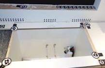
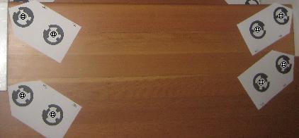
Ten coded-target points were printed and placed on a countertop,
2.
Five photos were taken of the area,
3.
The project was solved for 3D positions and angles.
4.
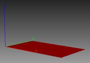
A Best-Fit Plane was created from 10 coded-target points.
5.
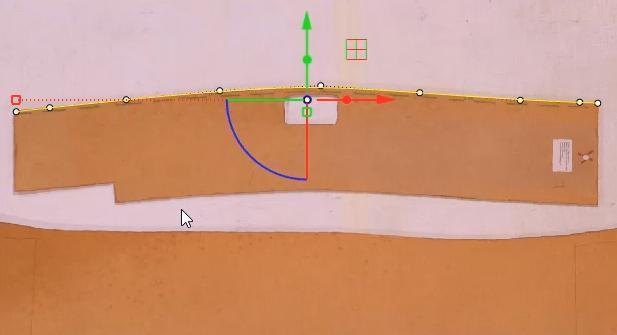
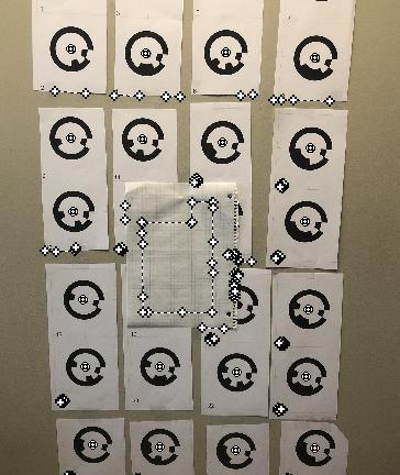
The sink openings were manually traced with Surface Draw Curves on the photograph with the best top-down view.
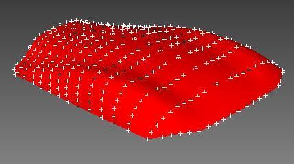
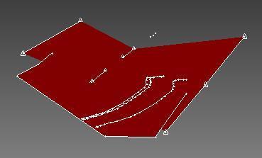
In the first image below, you can see five coded-target pairs (10 points total). In the second image, you can see the fitted Plane Surface and the Surface Draw markings.
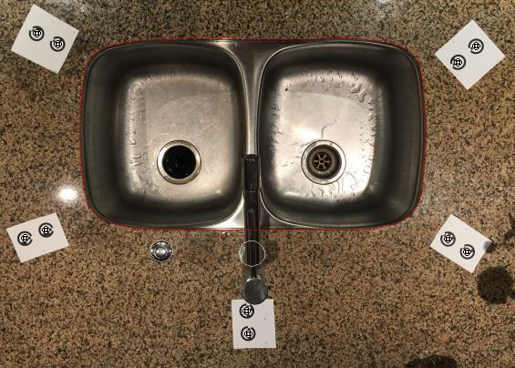
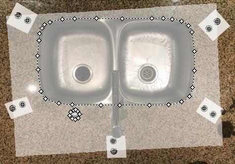
Note that as you draw the Surface Draw Curve on the photo, a series of points are marked and a curve is fit between them. Surface Draw can be done with poly-lines as well. Once the Surface Draw is complete, edits can be made to refine the curve by dragging the individual Surface Draw points.
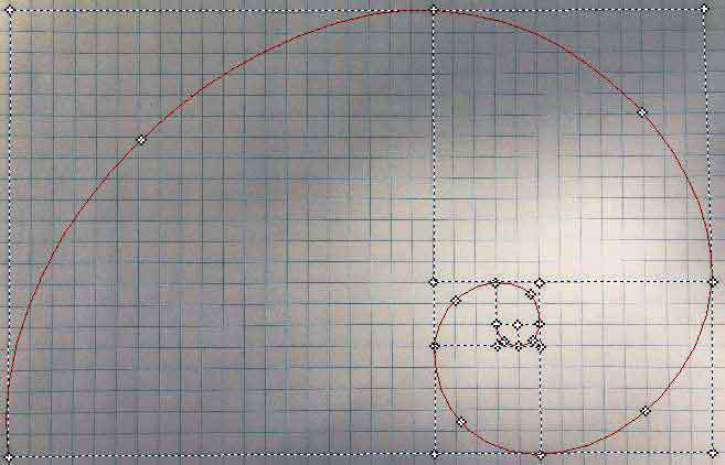
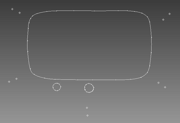
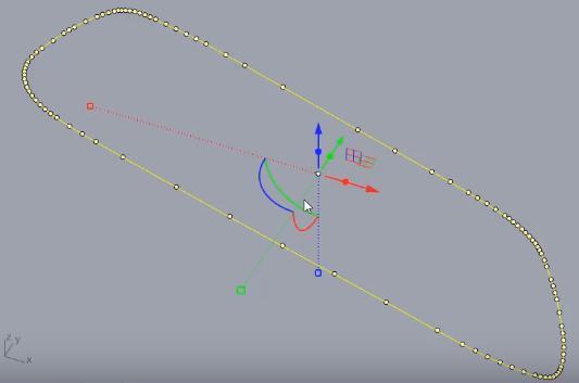
The Solution
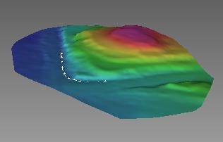
The shape’s 3D position is solved immediately – no processing required. The shape is shown below in the 3D View (on the right), and the 3D curve’s projection (in red) on a photo (on the left):
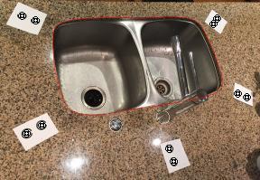
Verifying the projected position of the shape on various photos is an excellent way to ensure it is correct.
Note that as long as the Surface Draw curve/line is started on a Surface, the curve/line can be extended by marking the points off the surface anywhere on a photo.
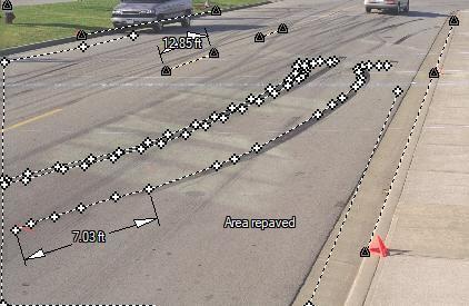
In manufacturing, CAD, and CNC use, accurate dimensions are essential. A scale is applied to the project (see the tutorial video on scale, or the tip video on multiple scales) to achieve these dimensions.
Export
The drawing can be exported and sent to a cutter, or to the next stage in the manufacturing workflow (see supported export formats). On the right, the model is shown in a CAD application ready for further processing.
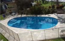
While this demonstration is a simple one of a dual sink, it is an illustration of similar shape drawing you might do to digitize template patterns, measure a boat deck, or to outline a swimming pool edge.
Demonstration Video
A video highlighting the use of Surface Draw in a coded target project can be found here: