Can Measurements be Made from Law Enforcement Body-Worn Camera Video?
This is a guest blog post written by collision instructor, and active LE officer, Bobby J. Mullinax. See bio below.
Why Use Body-Worn Camera Video for Measurements?

You may not need to use body-worn cameras as the photograph source for your photogrammetry project, but you may find yourself in a situation where you have to. How many times has a crash or crime scene investigator been tasked with putting together a complex puzzle, only to find out it has missing pieces? Sometimes at crash scenes injuries aren’t apparent to the initial officers on scene and photographs aren’t taken, and measurements aren’t logged. Or maybe that struck pedestrian is transported to the hospital before their location can be marked. Sometimes at a crime scene, initial officers must make the split-second decision to secure a weapon, or other evidence, to prevent its destruction or theft before the scene is contained. In the past we have used the best methods available to us, to try to put evidence back in its original locations, that may have been moved or overlooked.
As the usage of body-worn cameras by law enforcement continues to rise in North America, as well as other parts of the world, crash and crime scenes will now have a video witness of how the scene was when the first officers arrived. As more and more agencies come on board, more and more videos will be recorded by officers, and more and more evidence will be captured. So, in the case of that struck pedestrian that was transported quickly by emergency medical services, there is a greater chance that the pedestrian’s final rest was recorded by one of the first officers on scene. Now instead of using guesswork, or the recollection abilities of the officer, we can identify valuable evidence locations using the individual frames from the video and photogrammetry with PhotoModeler.
While this article discusses the interesting new area of measurement from body-worn camera video, a lot of the techniques and discussion also apply to images from other casual cameras, such as dashcams and smart phone cameras.
Will it Work?
This new method of extracting measurements and diagrams from body-worn cameras does come with a caveat. Body-worn cameras are produced with recording video in mind. While a body-worn camera like Stalker’s CopTrax records a 720p high definition video, with a size of 1280 x 720, an extracted still frame from the video yields only 921,600 pixels. This is the equivalent of just under a 1-megapixel camera. This is no fault of the camera itself, it’s how video resolution works. This body-worn camera is designed to record a high quality clear video, not to zoom in to see detail like a high resolution, high megapixel camera can. The question becomes, “Can we utilize this somewhat low-resolution image with photogrammetry and get results that we can confidently testify to in court?”
To test this, a couple of projects were completed with known results that we could compare the body-worn camera projects to.
Crash Scene Project

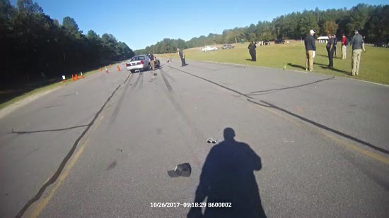
For this project a pedestrian crash test was conducted with a Simulaids mannequin, commonly referred to as a “Rescue Randy”, and a Ford Crown Victoria police interceptor. The Rescue Randy was wearing a hat and sunglasses and holding a bottle of water at impact. The Ford struck Randy at a speed of 40 miles per hour. Randy’s hat fell where he was standing at impact, and he lost his sunglasses, water bottle, and both shoes, on his way to his final rest position. In addition to the evidence left by Randy, the driver of the Ford began emergency braking, achieving four-wheel lockup and sliding to final rest.
After the crash test was complete, known measurements were obtained of the skid distance and the throw distance of the pedestrian. A walk-through of the collision scene was conducted while recording a body-worn camera video with the Stalker CopTrax, simulating an officer’s initial arrival and assessment of a collision scene.
The body-worn camera recording was viewed the following week, converted to still frame photographs, and one photograph was selected to be used in the PhotoModeler project.

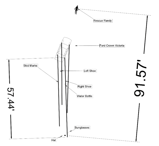
Using a scene survey and the external geometry explorer, the single still frame photograph was imported and solved as an Inverse Camera project in PhotoModeler. Once solved, PhotoModeler’s “mark surface points” feature was used to document the location of the hat, sunglasses, skid marks, bottle, both shoes, vehicle final rest, and Randy’s final rest. FARO Zone was then used to complete two diagrams of the collision scene. The first diagram is a traditional collision scene diagram identifying all relevant evidence and measurements of the pedestrian throw distance as well as the longest skid distance.
While the body-worn camera project was used to diagram all the evidence in this example, as if the scene was not documented initially, this project just as easily could have been used to locate only certain evidence that may have overlooked or compromised, such as the pedestrian being transported to the hospital, or the vehicle being moved. From the completed scene diagram a skid distance of 57.44 feet and a throw distance of 91.57 feet were obtained. At the crash test, a longest skid distance of 57.50 feet, and a throw distance of 91.80 feet were measured. Using the body-worn camera project data, speed estimates were conducted for the vehicle’s slide to a stop, as well as the pedestrian throw, which were within 1/10 of a mile per hour of the speed estimates calculated with the at-scene measured data.

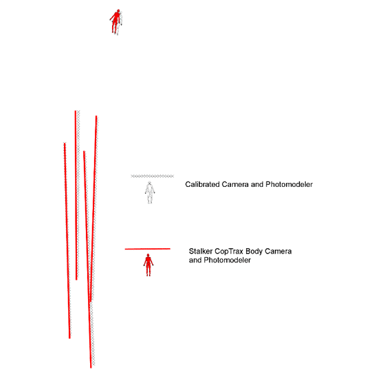
To see how well all the evidence aligned with its known locations, two diagrams were merged together using alignment points, which are not shown in the final diagram. One diagram was completed using a calibrated camera and multiple overlapping photos from different angles in PhotoModeler. The second diagram was completed using the single body-worn camera photograph and PhotoModeler. Once the diagrams were merged, the body-worn camera evidence was given a red color for easy identification and contrast
Crime Scene Project
Crash scenes are not the only opportunity for an investigator to utilize a body-worn camera video to help locate moved or undocumented evidence. Crime scene investigators can equally benefit from this technology.
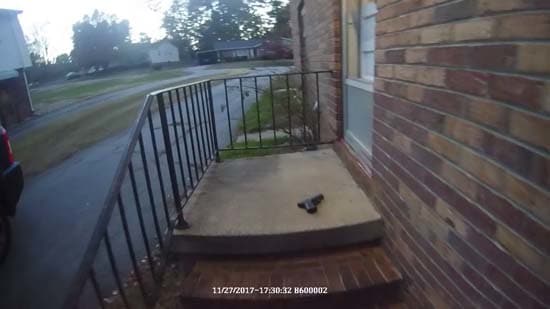
In this example, a gun was placed at the entrance of a single-family residence. A body-worn camera video was then recorded with the CopTrax camera of the officer’s initial approach of the entryway. While this video was not recorded at an actual crime scene, it was set up to simulate an officer that encounters a weapon. The officer does not have enough manpower to secure the scene fully and must secure the weapon and enter the residence. The video was also recorded under less than studio-perfect conditions, with the video being shot as the sun was beginning to set.

Since this was not an actual crime scene, I had the luxury of first documenting where the weapon was located, to see how the results matched up. In PhotoModeler, the still frame from the body-worn camera was loaded as an unknown camera, the camera parameters were solved, the photograph oriented, and the location of the weapon marked. Like the pedestrian collision example, everything was then imported into FARO Zone and a diagram completed.
As seen below, the location of the weapon was documented two ways: a) using PhotoModeler with a calibrated camera and multiple overlapping photos, and b) using PhotoModeler with the single Stalker CopTrax body-worn camera photo. The inset picture is a closeup of both weapon locations. The two locations overlay nicely with the noticeable differences being in the trigger guard and grip, which are minimal. To check the accuracy of the project, using the body-worn camera project the length of the concrete step base was measured with a length of 51.10 inches. A measurement taken by hand, yielded a length of 50.75 inches, a difference of only .35 inch, or a little under 9 millimeters.

Conclusions
Based on this testing and research, it is possible to get exceptional results with PhotoModeler and extracted still frames from body-worn camera videos to determine position of evidence, or to diagram scenes which were not documented. A few tips to help make this task easier:
- Avoid, if possible, using areas of the photograph which are highly pixelated.
- Even if you have access to the body-worn camera for calibration, it’s generally easier to use a scene survey or another photogrammetry project, and bring in a few of the body-worn camera still frames to solve your project like you would any other unknown camera project.
—
Bobby J. Mullinax is a full-time instructor at the South Carolina Criminal Justice Academy where he teaches all levels of collision reconstruction, and is responsible for the state’s Pedestrian-Bicycle program. In addition to his academy duties, he is a part time instructor for the Traffic Safety Training Center. He has lectured on the topic of reconstruction from body-worn camera videos at many conferences. He has been in law enforcement since 2007 and currently lives in Spartanburg, South Carolina.
