
Accuracy of Pile Volume Measurement with Photogrammetry
 Accurate volume measurement of piles of material is important in a number of applications, such as: stock pile inventory management, volumes of tailing piles, volume of organic materials in composting operations, quarry pit size, mine reclamation, etc.
These piles are difficult to measure due to their size, difficulty of traversing, and non-uniform shapes. The advent of UAV (unmanned aerial vehicles) with cameras, and software for extracting surface shape from imagery, such as PhotoModeler, have greatly eased this task.
A key factor in using this technology in real-world applications is volume accuracy.
This article highlights a series of PhotoModeler Scanner (now Premium) experiments using SmartMatch and Dense Surface Modeling (DSM) to model a small sand pile with a known volume to gauge volume measurement accuracy.
Although the projects in these experiments are mock-ups using a small known volume of sand on a desktop, the concepts can easily be applied to material piles in the hundreds or thousands of cubic yards or meters. The only difference is how the camera is carried, with a UAV / drone or full-size aircraft platform for measuring large piles.
The results from PhotoModeler Scanner (now Premium) demonstrate accuracy that is safely within the range of expectations and goals given to us by customers in this application area. Compared to other methods that rely on a relatively low number of survey points to try to represent a complex pile shape, PhotoModeler Scanner produces more accurate volumes from real-world profiles, on a more frequent, timely and cost-effective basis, with greater safety in a live operations environment.

Experiment Setup
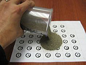
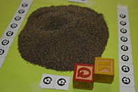
A known volume of sand (400 cm3) was poured onto a sheet of paper with printed coded targets. The coded targets on the sheet are used to establish the coordinate system (i.e. the scale, rotation, and translation, and therefore the XY ground plane). Although coded targets were used in this project, any points could be used to establish the coordinate system, whether targets or user-marked features. High contrast circular targets do provide higher marking accuracy, and well-marked points are recommended when setting the project scale, but in a real world situation, targets may not be practical. Distinct features can also be used for point marking and referencing.
Determining the ground plane is very important to producing a meaningful result. With this small experiment it is clear the sand sits on top of a sheet of paper on a desk, but in real world cases, the ground plane determination may not be as easy. When carrying out these types of measurement tasks you need to give careful thought to your ground plane, and esp. when you are doing comparison measurements over time (e.g. will the same ground plane be dectable over time?).
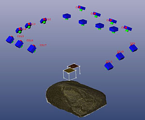
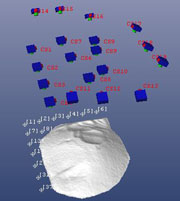
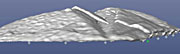
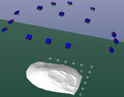
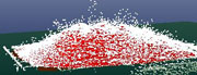
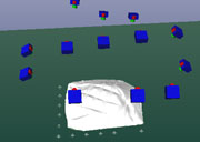
A series of photos of the sand pile were taken such that there was suitable overlap and the texture was captured high in detail with targets visible in enough photos. Shown below is a typical setup. The toy letter blocks were placed to judge vertical accuracy.
Distance between targets was known. Photos were taken in a series of rows with suitable overlap as shown in the image at the top of this article. Technically, this model could have been created with as few as 2 to 3 photos taken from a higher position, but to mock up a project that simulates, for example, aerial photography of a stockpile, the photos were taken along ‘flight paths’.
Project Steps
The following steps outline the basic approach the various test projects:
- Calibrate the cameras using the single sheet method at a distance and focus similar to the project photographs.
- Take a series of photos of the sand pile scene, ensuring suitable overlap and base (separation between cameras) to height ratios suited to SmartMatch/DSM processing. Upload to the PC.
- Start a new Automated Project (SmartPoints Project) and load the photos into the project. Camera matching ensured that the photos were automatically assigned the correct calibrated camera from the camera library.
- Run SmartMatch – ensure photos orient to capture entire scene of interest. Note the coded targets were not used for orientation to better simulate real world scenarios.
- Run DSM – with good overlap and good random texture, the resulting DSM PointMeshes should be relatively noise-free for best results.
- Triangulate the PointMeshes.
- Run Automarking to mark the coded targets (or mark features and manually reference the points).
- Set up the coordinate system based on the 3D target points (to define the X axis, the Y axis, the scale (multiple scales ideally), and the origin). This also establishes the ground plane.
- If multiple scales were used, open the Check Distances table to ensure project accuracy is acceptable.
- Trim the triangulated mesh where the mesh meets the ground plane (in many cases would not be needed since Measure Tool shows volume above ground plane, but here extra noise from the targets raised the extended surface above the ground plane and misrepresented the volume).
- Use the Measure Tool and select the triangulated mesh to find the volume.
Project Results
The experimental results are summarized below. Each row shows one PhotoModeler project for one experiment and the resulting volume measurement, the volume error and a short summary:
|
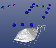
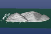
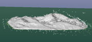
3D Viewer Screen Capture |
PhotoModeler Calculated Volume over XY Plane |
% Difference to 400 cm3 |
Notes |
|
|
405 cm3 |
1.25% over |
Nikon D7100, excellent DSM result, little noise, varied pile shape. |
|
|
387 cm3 |
3.25% under |
iPhone 4 camera, some blur in images. |
|
|
380 cm3 |
5% under |
iPhone 4, flatter pile. |
|
|
407 cm3 |
1.75% over |
Nikon D7100, manually marked scale points. |
|
|
598 cm3 |
50% over |
iPhone 4 camera, noisy pointmesh, overlapping triangulated pointmesh (visible in lower screen capture), big residual on scale points (suggests poor orientation). |
|
|
377 cm3 |
6.75% under |
iPhone 4 camera, images from automatically extracted video frames. |
|
|
368 cm3 |
8% under |
Nikon D7100, manually marked scale points, depth of field causes blur in portions of images, noisy point mesh. |
|
|
416 cm3 |
4% over |
iPhone 4 camera, some blur in images, relatively high residual for scale point (11) suggesting sub-optimal orientation. |
|
|
426 cm3 |
6.5% over |
Canon SD 1000, some blur results in pointmesh noise. |
|
|
408 cm3 |
2% over |
Nikon D7100, excellent DSM result, little noise, varied pile shape. |
Summary
These experiments show that with a well set up project -in terms of an accurate coordinate system, well positioned cameras, and low-noise DSMs – PhotoModeler can accurately measure volume of a material pile. The accuracy here is within +/- 5% for the high quality projects which is very good given the standard against which the comparison was done. Outside of the one outlier, even some of the nosier results produced volumes within +/- 10% of our standard.
As can be seen in the project results and the one outlier, the accuracy of volume measurement can be sensitive to project problems, especially when a triangulating a number of noisy meshes. To evaluate a result we need to look at the noise in the mesh(es), multiple mesh alignment, the agreement of the comparison scales, the size of the precision figures, and the residual error values, before relying on the volume measurement.
With careful review of the statistics given by PhotoModeler, we can be confident that the PhotoModeler volume measurement is within measurement tolerance.
Have a look at some of the real world Geology and Mining and Surveying examples on the PhotoModeler web site.