
Capturing Motion with Photogrammetry and PhotoModeler
In this post I highlight the practical uses of PhotoModeler Motion (PMM), and feature two example projects.
PhotoModeler Motion / PMM is the top of the PhotoModeler product line. It brings the time dimension into your measurement and modeling projects. PMM includes all features of PhotoModeler and PhotoModeler Scanner, and adds modeling of a dynamic object or scene over time – a PMM project encapsulates a series of mini projects – one per ‘epoch’, based on the frame rate of your photography or video.
Some uses of PMM are a) measuring the effect of a load on a material over time, b) modeling the change in shape of an object or scene due to erosion or human action, or c) measuring the distance key points move over time. One of the key features of PMM is the Tracking Tool which allows for target points to be automatically tracked and measured over time.
There are two types of PMM projects:
- Type 1: This project uses synchronized cameras to take photos of a continuously moving object/scene at an interval proportional to the rate of change in the scene. Typically a Type 1 project will detect, mark and track dot targets, but SmartMatch and DSM can also be used to model a changing shape.
- Type 2: This project is suitable for a ‘stop-motion’ type of scene, where a single camera can be moved around the scene while the scene is stationary.
This blog post focuses on two Type 1 project examples.
Type 1 Project Setup
A Type 1 project requires a system of synchronized cameras, each firmly fixed in position. The synchronization needs to be tight since the process involves generating a distinct model at each time frame/epoch, and like a regular PhotoModeler project, target points must not move during photography. If the object being modelled is moving quickly then high speed cameras with accurate synchronization will be required so the object is ‘frozen in time’.
The cameras in a Type 1 project must not move between epochs since the camera orientations are established in the first epoch and assumed to be constant.
The frame rate of the synchronized camera setup will be proportional to the rate of change in the scene and the density of the targets. A highly dynamic scene will require a high frame rate with photos at a resolution that allows for reliable target marking and tracking. Between epochs, target dots should typically move less distance on the image than the spacing of the targets. E.g. if the smallest inter dot distance on any photo is 100 pixels, then the dots should not move more than 100 pixels frame to frame.
Careful consideration is then needed when planning out target dot spacing, camera frame rate, and camera synchronization based on the subject shape, camera position and the subject speed.
Project Steps
Here is how I set up my Type 1 projects:
- Take a series of synchronized photos and upload to my computer. Rename/categorize the photos from each camera appropriately (you can either use an image file naming system, or a sub-folder system containing each epoch’s images – naming conventions are described in the Help document). I used an image file naming system.
- Start a new PMM project using PhotoModeler’s New Project Wizard and load the photos into the project. I used camera tag matching (also described in the Help document) to ensure that photos were automatically assigned the correct calibrated camera in my camera library.
- Run Automatic Target Marking in the first epoch, marking the Coded Targets first, then the non-coded dot targets. Process the project to orient the photos based on the coded targets.
- Run auto-referencing in the first epoch to reference non-coded targets. Reprocess the project to fine tune the orientation based on the larger set of points. Ensure the project in this first epoch is solving well with a low residual.
- Scale the project.
- Run Tracking to track the points through all epochs. Ensure all points of interest are tracked through all epochs.
- Lastly I measured and analyzed the results.
Sample Project Descriptions
Project 1 – Fan Blades
Using three synchronized cameras, I tracked and measured the movement of a series of non-coded target points marked on the blades of a fan as the fan slowly rotated counter-clockwise. The coded target points around the perimeter were more or less stationary and not necessary for measurement (these coded targets help with project setup and allow for quick camera orientation, and auto-referencing of non-coded targets).
Here’s a photo of the setup, showing the target pattern and the three camera configuration:
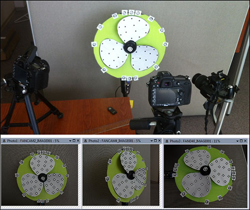
I used a simple synchronization system, using the Nikon infra-red remote control to trigger each of the cameras simultaneously. For higher accuracy, especially when the rate of change is high, a more sophisticated synchronization system would be required. Here the blade was moved very slowly. This Knowledge Base article describes synchronization options: Synchronizing Cameras for use with PhotoModeler Motion
The following animation exported out of PMM shows the points (and surfaces) tracked through 95 epochs:
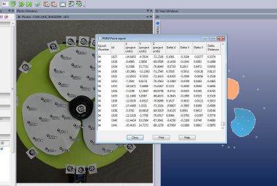
Using the Point Report I can track the 3D change of each tracked point between epochs:
Project 2 – Rubber Membrane
Using four cameras in a simulated synchronized setup, I measured the effect of increasing amounts of load over time on a rubber membrane. The membrane was covered with equally spaced non-coded dot targets. As in the previously described project, the coded target points around the perimeter were stationary and helped initial setup. The non-coded targets were tracked over 25 epochs.

In this project the load was incrementally increased (approximately 30g per epoch) allowing me to take photos every second or so. You can see in the animation below the effect of the load on the membrane and the resulting effect of the points’ 3D positions over time.
Summary
PhotoModeler Motion can be used in a variety of projects with high accuracy requirements where movement is involved. You can measure the effect of movement or load in X, Y and Z. The projects described in this post are intended to highlight the features of PMM and to show its applicability in real world scenarios.
As demonstrated in the first project, PMM can be used when you need to ensure stability or the structural integrity of a component (e.g., machinery or mechanical testing, trajectory testing, vibration analysis etc.).
As in the second example project, PMM can be used to measure the stress at various locations on a surface depending on proximity to the load (e.g., wind or solar sails, protective sheathing, building materials, erosion tests etc.).
There are other ways of using PMM with DSM/SmartMatch and/or Type 2 projects. Examples of these types of projects are shown on the PMM webpage.