
Using a Dropcam for Forensics and 3D Measurement
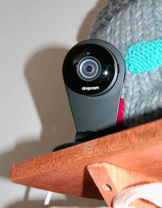
The Dropcam security camera is one of several easy-to-use IP cameras on the market for self-monitoring security systems.
This article describes a forensic simulation using Dropcam imagery, and the 3D-from-photos software, PhotoModeler. PhotoModeler is the most comprehensive solution, at any price, for working with images from a variety of sources to produce accurate 3D measurements and models in many different fields.
In this example, the height of a burglary suspect is measured in a crime scene simulation, and the location of a step ladder is measured in a workplace accident scene simulation. These are carried out in a retail shop with the shop owner’s own Dropcams.
These types of forensic measurement tasks can be carried out a number of ways in PhotoModeler; this article describes the following approaches:
- Single-Photo Inverse Camera
- Single-Photo Calibrated Camera (orientation by control points)
- Two-Photo Inverse Camera with Marking and Referencing
- Two-Photo Calibrated Camera with Marking and Referencing
Image Acquisition and Survey
Dropcams send surveillance footage online to a server to be reviewed in a timeline by the owner. A motion detection feature alerts the owner of unexpected activity.
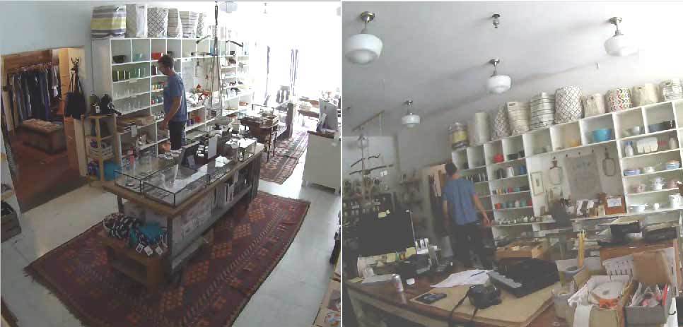
In this simulation, a suspect broke and entered the premises, motion was detected, the owner notified, and the online timeline was inspected to detect the suspect in various locations within the premises. Frames were extracted from the recorded video:
Note: click on any image in this blog post to view the full resolution version.
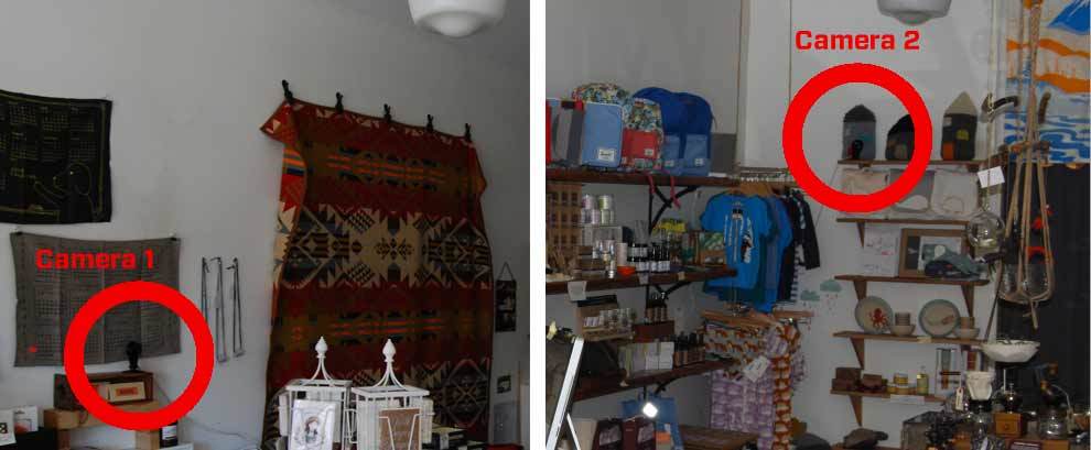
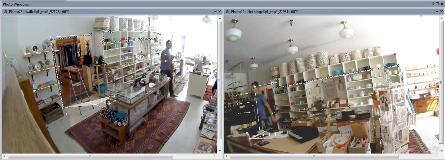
In this case the shop owner has two Dropcams. The cameras are conveniently positioned to capture the scene with good angle separation:
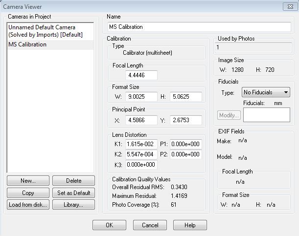
The specification of these cameras (focal length, image sensor size, lens distortion) are ‘unknown’, that is, they are uncalibrated. In addition, they write no data describing the specifications to EXIF headers so an approximate camera definition isn’t possible. For an accurate forensic reconstruction the cameras’ focal lengths and other camera parameters need to be calculated by PhotoModeler, either by ‘Inverse Camera’ or a camera calibration.
Initial Survey
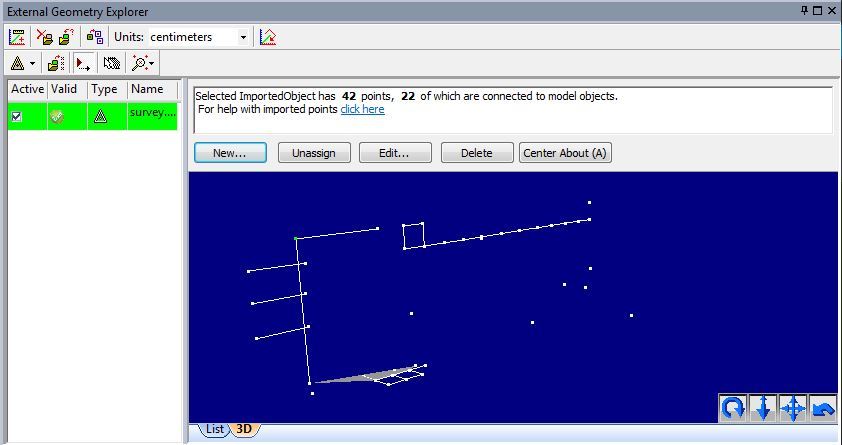
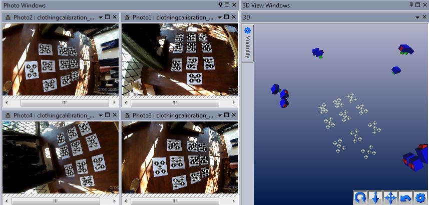
To start the forensic investigation, the shop interior was first surveyed using PhotoModeler with a calibrated camera, although any other accurate 3D survey method could be used. This was a standard PhotoModeler 3D modeling project:
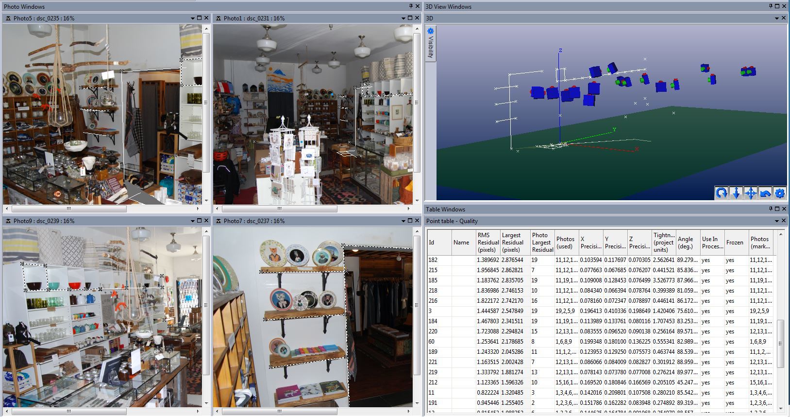
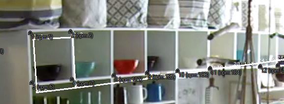
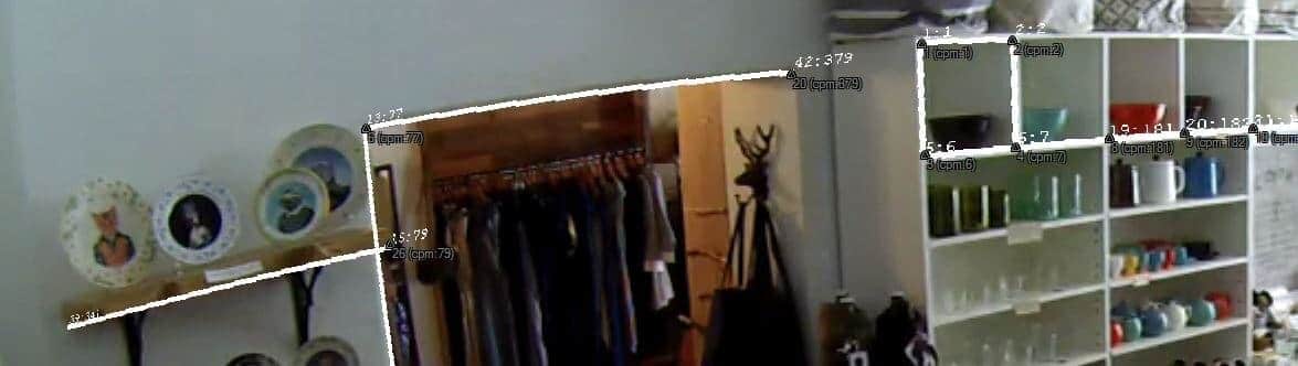
Key features of the shop’s interior were modeled, and a coordinate system set up, so that the survey/control points could be assigned to common points marked on unchanged features in the Dropcam images. Features visible in both the surveillance and survey photos, such as the shelving units, display cases/tables, floor tiles etc. were marked in the photos, and used to set up a series of control points.
Single Photo Inverse Camera
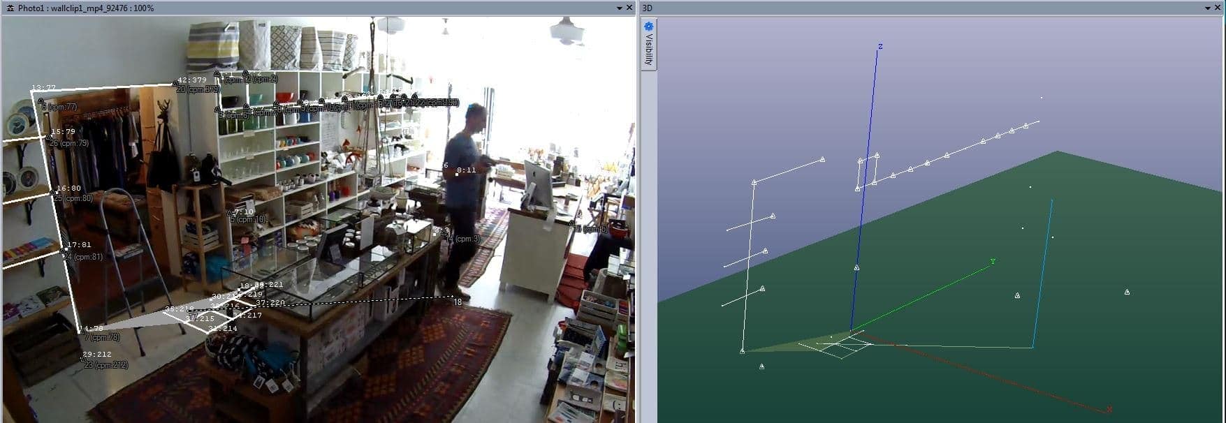
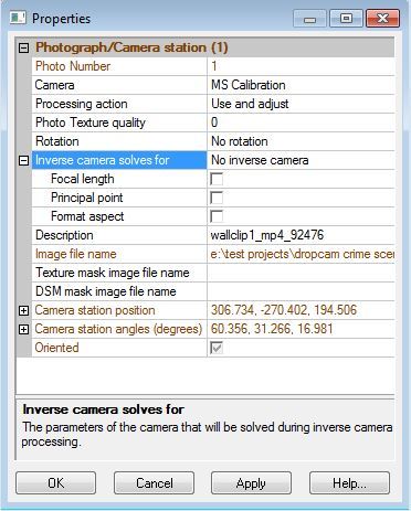
The first approach used a single-photo Inverse Camera method. This method is suited to cases limited to a single photo/camera (fairly typical in a project like this). The control data created in the initial survey, as described above, is imported, and points are marked at the surveyed locations on the single Dropcam image.
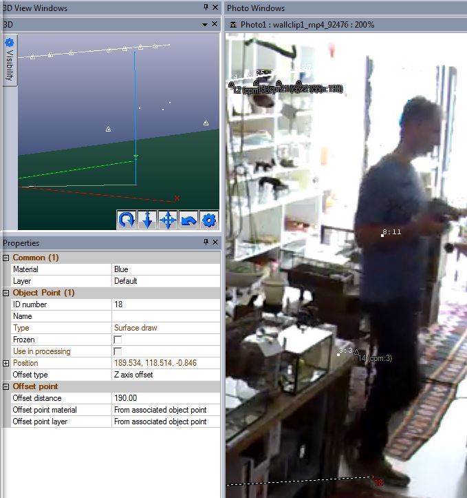
The resulting height is shown at 190cm by PhotoModeler’s measure tool. [†projection means displaying 3D data back onto a photograph once the camera position and parameters have been solved. Closeness of projected data to the matching image feature in a photo is a good measure of how well the project has solved.]
Though control points were used and effort was made to mark the points carefully, the resolution of the security camera made it difficult to pinpoint point locations. Also, and more significantly, these cameras have wide angle lenses (to capture as much of a scene as possible) and have a large amount of lens distortion which the Inverse Camera method does not solve. The Inverse Camera result is a best approximate solution that may be suitable for some purposes. Methods below describe how to improve on this.
Usually the alignment of 3D projected positions of lines and points will be the best indicator of ‘fit’. For points, this alignment/fit is numerically represented as the ‘point marking residual’ (also see this tip video). This project showed a loose fit. For example, notice how the projected lines do not align perfectly with the shelf, and also notice the curve in the shelf due to lens distortion:
Without a calibration, this method can at least provide an approximate solution when no other resources are available. How can this be improved?
Calibrate the Dropcam
Having access to the scene and its security camera(s) allowed for a camera calibration. A multisheet calibration can be carried out by placing the target pattern on the floor and moving the camera around it in the usual camera calibration positions (multi-sheet calibration tutorial here):
The relatively low image resolution of the cameras made for a difficult calibration at this distance, but supplementing the automated tools with some manual target marking and referencing, a reasonable solution was obtained, including a solution for the K1 and K2 lens distortion parameters.
After re-processing the result was a much better alignment of the imported data with the photo.
The offset height property of the surface draw point was adjusted downward to re-align the projected offset point with the suspect’s top of head. The revised suspect height was 188 cm.
Note that in some cases even if access to the actual Dropcams is not available, a calibration of a Dropcam of similar specs could be substituted and provide a superior result to Inverse Camera alone.
Two Surveillance Photos
The site had two Dropcam security cameras monitoring the space, which allowed the project to also be carried out as a two photo Inverse Camera project. Starting with the assumption that the cameras were not available for calibration, both photos need to be solved using control points and Inverse Camera.
Two photo solutions are generally recommended over single photo solutions when available. The two photos allow for additional points to be solved anywhere in 3D space and allow for cross checking.
One issue with using multiple cameras, when capturing moving objects, is synchronization. Although each camera’s video has a time-stamp (showing hours:minutes:seconds), synchronization may not be tight enough and even a slow moving suspect may not appear in each image in the exact same location; referencing points on a moving object in multiple photos can be unreliable.
Shown below are two image stills with control points marked, and 3D geometry projected onto the photos. The suspect is shown from the two camera angles:
Frames from the video were selected where the suspect was most reliably positioned, and where he was relatively motionless (to avoid issues with video synchronization). Though the feet aren’t visible in both photos, because the model is in the control-based coordinate system with the ground plane on the floor (i.e. Z=0), we can mark and reference a point on the top of the suspect’s head and check height using the Z coordinate. In this case, it worked out to 188.8cm, quite close to the measurements in the other approaches.
Replacing the inverse cameras with the calibrated camera again improved the model fit. The Z coordinate measurement dropped slightly to 188cm – more in line with the single photo calibrated case above.
Modeling other objects shown in the surveillance images
Having the luxury of two photos allows for marking and referencing of additional points between the two unknown photos. This is especially useful when the scene has changed between the time of the incident and the survey. Of course having more than two photos would be ideal, but two photos capturing a scene is almost always better than one!
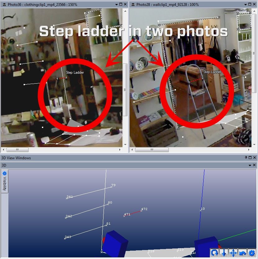
Two points on the ladder were referenced in the two surveillance photos, and the ladder’s location was measured. PhotoModeler can display measurements and drawings of the ladder location relative the doorway.
Further Refine a Camera – Field/Self Calibration
PhotoModeler also has ways to fine tune a camera when a project has enough points marked with good spread. In projects with multiple photos and taken with a single camera, Field Calibration can be used to fine tune a camera definition based on the data in the project. In projects with multiple cameras, such as the projects described in this article, Self Calibration can be used to generate an implicit camera refined for each image in the project. These camera optimizations are enabled on the Processing dialog and can often improve a result, because the process tries to account for a camera’s lens distortion. Camera optimization should generally be reserved for projects where the initial solution is strong, so that the camera definition is based on a solid model.
Summary
The various approaches showed a height measurement quite close to actual, with the calibrated version coming in closest, not surprisingly. The suspect’s height is known to be 188cm.
A project like this could be completed soon after motion is detected, and a suspect description, including an accurate height, could be sent to law enforcement or used in a forensic reconstruction to build a criminal case.
This article shows how it can be used with imagery from a Dropcam surveillance camera to measure key dimensions for use in forensics, crime scene and accident reconstruction.