
- /
- /
- /
- /
Angle Measurements of Lines, Cylinders and Edges
When a line/cylinder/edge is selected, the Measurement Pane shows angle measurements relative to the coordinate axes. With two lines selected, the Measurement Pane also shows the minimum angle between the lines (the lines are extended in both directions and translated to intersect).
This article describes how these angles relative to the coordinate axes are computed. For simplicity, this article refers to lines only but the same applies to cylinder center lines and edges.
When selecting a line, the Measurement Pane shows the minimum angle between the line and the X, Y and Z axis. It is a full 3D measurement not a measurement in any of the projections.
A display in the Measurement Pane for a selected line might look like:
Angles relative to axis x:1.0 y:88.9 z:89.9 degrees
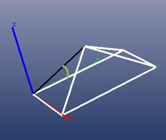
Here is an example to visualize. This line (circled in yellow), between points 7 and 8 on the box, is almost parallel with the X axis:
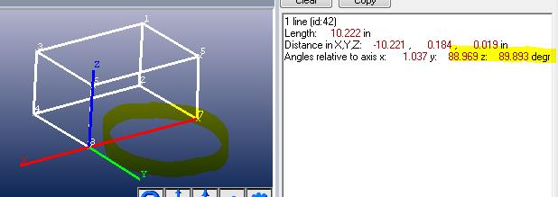
Hence the angle with the X axis is almost zero (parallel) and almost 90 degrees (perpendicular) to the other two coordinate axes.
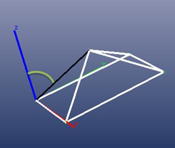
Here’s another example with the line not parallel to one of the axes (black line on a pyramid):
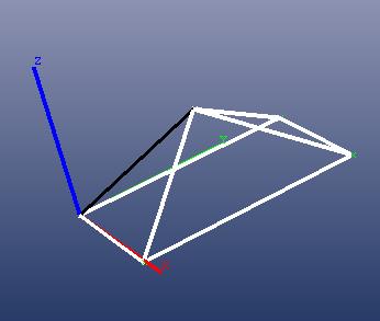
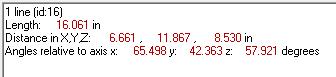
PhotoModeler shows the angle of the black line as:
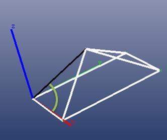
The angle with the X axis can be seen here with the green arc. The arc lies in the plane defined by the X axis and the selected line. This is the mathematical minimum angle between the line and the X axis vector in 3D space:
With the Y axis:
With the Z axis:
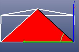
Another way to study the angle is to align a view with the plane through line and the axis under consideration. For example here is a view that is straight on to the plane formed by the Y axis and the black line (the plane is shown in red and the view is parallel to this red plane). The angle shown here is the measured angle between the line and the Y axis:
To further illustrate and clarify below we show the standard orthographic projections: ‘top’, ‘right, and ‘front’. These views project the line into another 2D space and do NOT show the minimum 3D angle between the black line and the axes – because the line is not in one of the XY, YZ, or XZ coordinate planes.
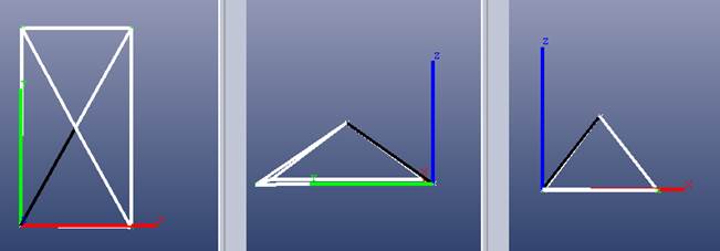
Standard Orthographic Views: Not how measurements of angled lines are done
If you need the projected angle and know what PhotoModeler provides, you will need to project the 3D end points onto the 2D plane that you want to measure. For example to get the points projected on the XY plane (typically ‘top view’) ignore the Z values of the line end points. If you plot these 2 points you can use trigonometry to figure out the angle of interest. For an XZ projection, drop the Y values from the line’s end points and use these 2D values to calculate the angle.