All Tutorials and Tip Videos

All tutorials and tip videos. Grouped and sorted alphabetically.


Current Tutorials

Automated Coded Targets

How to run an automatic project with RAD coded targets and offset points. Automatic marking and automatic referencing described as well.

Automating Tracing of Pattern Lines and Edges

This video shows how to set up and use the Auto-trace tool for semi-automated tracing of pattern lines and edges. Contrary to the video's title, it is no longer in beta.

Boat Deck Measurement - Continuing Work

4. Continue to learn how to use PhotoModeler for adding new panels, verifying measurements, using tools such as image enhance, and how to flatten from a 3D model for a 2D CAD export.

Back to top


Boat Deck Measurement - On-boat Work

2. For those taking photographs and laying targets on a boat in preparation for PhotoModeler project work.

Boat Deck Measurement - PhotoModeler Work

3. For those that will use the PhotoModeler software to convert the photographs into tracings that get exported to CAD. See also Outlines.

Calibration Multi-sheet

How to pre-calibrate a camera for the most accurate results. Solving for focal length, principle point, and lens distortion.

Back to top


Car Crush

Measure the crush of a vehicle from photos taken by an unknown camera, using an exemplar vehicle.

Check Distances

How to use check distances and points to check accuracy or to compare to known values.

Crush from an Exemplar

Measuring the crush of a vehicle from photos of an unknown source by adding them to a solved project of an exemplar and freezing the points.

Back to top


Create Coded Targets

Demonstrates how to print Coded Targets from within PhotoModeler, and other options for creating and using Coded Targets.

Creating a 2D Template Project with a Mounted Camera

Describes how to create a new mounted-camera setup. The video assumes you have a mount ready for the camera but starts with the camera un-mounted.

Creating a 2D Template Project with a Moving Camera

Describes how to create a setup for one-off pattern digitizing jobs. This might be the video you send to a remote site for the quickest way to get an accurate configuration.

Back to top


Default Plane Offset

When doing Surface Draw on a plane that does not match the true surface, due to targets with thickness, this video helps with setting up a default thickness/offset for the target planes.

Digital Templating for Marine Canvas with Your Camera

An introduction to how PhotoModeler and a camera can be used to measure and do 3D templating for marine canvas work.

Digitizing a 2D Template in a Reusable Setup

This video is a good step by step introduction to the process of setting up and digitizing a 2D template, start to finish. It is focused on a setup with a moving (un-mounted) camera that can be reused multiple times for different patterns. The method shown can also be used with a mounted camera, where the camera or table might move.

Back to top


Digitizing a 2D Template Pattern

This video describes how to digitize a template pattern once the setup has been completed. It describes how to create the 2D data (lines or corrected photos), and how to export to your favorite CAD package. Also see the Auto-Trace video.

Establishing Vehicle Speed from Surveillance Video

3rd-party video. This video, created by Ben Molnar of Lightpoint Data, demonstrates how to use a laser scan of a scene to extract data (such as vehicle speed) from video surveillance footage. Note that the video frame extraction can be done by PhotoModeler or VLC as well.

Export Aligned Images to Blender

Correct photos for lens distortion and export to Blender to use as a background image plates for other modeling or animation.

Back to top


Find Surface Trace Photos

Help answer, "What photo do I continue my tracing on?" when working with Outlines and Surface Draw in a multi-photo project.

Fitted Plane Rotation and Size

A Plane Surface fitted to 3D points is a powerful capability in PhotoModeler. This video demonstrates this plane type, and how one can control the plane's 3D rotation and its trim size.

Getting Started with Boat Deck Measurement

1. For those first learning to use PhotoModeler to measure boat deck panels. It takes you through a project that you can do at your office or home - so you can first learn the basics.

Back to top


Getting Started with Marine Canvas

The first steps in any marine canvas project are described

Height Offset Dynamic Measurement

Single photo height measurement above a plane (often done in security camera perp height estimation) can now be done in a more dynamic way by dragging the point.

Interpreting the Automated Project Processing Summary

There is a lot of useful feedback given by the processing dialog for Coded Target processing. This video show how to interpert that information.

Back to top


Introducing Bent Tubes

Bent Tubes are used to model cylinderical tubes that have bends in them - such as those that hold up marine canvas. This video introduces them and shows how to create.

Introduction to 2D Template Digitizing

This video introduces the concept of digitizing and capturing template patterns using a camera and PhotoModeler.

Manual Points Project

For manual marked projects (or when you need to add manual marks and references to an automated project). Covers completing a simple manual points-based project start to finish.

Back to top


Marine Canvas in Rhino CAD

Demonstrates techniques for handling canvas measurement data (points, lines and bent tubes) in Rhino CAD to produce canvas panels.

Measure

Demonstrates how to use the Measure pane. Display various types of measurements of objects and between objects.

Measuring Points, Lines, and Curves for Marine Canvas

This video builds on the Getting Started canvas video and describes how to add points and other objects needed to complete a canvas measurement ready for CAD export.

Back to top


Merging Marine Deck Projects in CAD

For larger boat deck projects you may need to split into two or more projects. This video describes how to merge this in CAD.

Merging Two or More Coded Target Projects

Describes how to reuse Coded Targets in multiple projects and merge the projects based on some subset of shared targets. Music by Bensound.com.

Modeling Boat Decks without Letter Sheets

An overview of how to extract 2D tracings of flat decking panels using non-Letter Sheet targets.

Back to top


Multiple Scales

An overview of how to use and set up more than one scale distance in a project.

Outlines

An overview of the Outline surface drawing methods and tools. CAD-like drawing capabilities for high quality tracings. See also Boat Deck Tracing.

Outlines - additional features

Three additional features for Outlines (multiple fillet, set radius, corner to fillet).

Back to top


Outlines Manipulation

Four tools to manipulate whole Outlines: Duplicate, Mirror, Move and Rotate.

Outline Split

Split an Outline Line or Spline into two so other elements can be added, or assigned to different surfaces.

Point Auto-detect

Improve the speed of manual marking and referencing using the Point Auto-detect mode. Mark a point in a single photo, and have it automatically detected, marked, and referenced in other photos.

Back to top


Properties

Demonstrates the Properties pane. All object have properties and this pane allows you to modify them.

Ray Pinning

Shows how to manually place, or pin to rays/2D points, a point cloud in a single photo project.

Road Diagram

Creating a diagram of a road scene using multiple photos and a calibrated camera.

Back to top


Scale / Rotate / Translate

Use of the 'Imports and Coordinate Systems' tool to set up Scales, Rotations, and Translations.

Single Photo Security Camera

Getting measurements from a single security camera with high lens distortion. Describes steps-by-step, and how to quality checks.

Sloped Deck Panels

How to handle panels on a boat deck that are sloped relative to the main plane, and you are using the Surface Draw tracing method.

Back to top


SmartMatch and DSM

Introduction of the SmartMatch tool and Dense Surface Modeling.

Some of my Decking Photos did not Orient

If you encounter a decking project where some of your photos did not orient (have a Red X on the image chip), this video will assist.

Surface Draw Overview

A deep dive into all things Surface Draw. Where and how Surface Draw is used.

Back to top


Surface Path Mode

One of the common simple Surfaces in PhotoModeler is the Path surface. This tutorial describes how to use Surface Path Mode.

Working with Small Deck Panels

Explains a few methods for dealing with small deck panels that are smaller than can hold three normal targets. Also how to manually fix a panel without enough targets.

UAV/Drone 1 Introduction

Introduction of the typical first processing steps of a UAV / drone project. Also see all UAV tutorial section below.

Back to top


UAV/Drone 2 Dense Surface

Demonstrates how to create a high density surface using the MVS tools based on the UAV Introduction data set.

UAV/Drone 3 Orthophotos

Follow on from UAV Intro. Describes creating an orthophoto in a UAS project.

User Interface Overview

Covers PhotoModeler's interface, Ribbon, status bar, and Windows pane interface, and customization.

Back to top


Using a Laser Scanned Exemplar to Model Crush

3rd-party video. This video, created by Lou Peck of Lightpoint Data, demonstrates how to use a vehicle laser scan to model accident crush from photos.

Using 3D Import Surface Pinning and LIDAR Data to Solve Vehicle Speed

The Surface Draw based import pinning mode is used to pull in a LIDAR scan of a vehicle to pin to a photo and a surface from a scene scan. And vehicle speed is estimated.


Back to top


Older User Interface

Calibration Single Sheet - 1

How to calibrate a camera using the single sheet method. Note the video shows a large single sheet but can be done with small sheet too if you model small objects.

Calibration Single Sheet - 2

Follow on video to number 1 above. [Recorded with an older version but the steps are very similar in latest.]

Curves - Referenced

How to create Curves from multiple referenced 2D curve marks.

Back to top


Curves - Through Points

How to create and fit Curves from existing 3D points.

Field Calibration

How to calibrating a camera at same time as solving a project - called field calibrating.

Materials

Demonstrates how Materials (colors, textures, surface appearance) work.

Back to top


Photo Zoom

Demonstrates the various tools for zooming and panning photograph views.

PointMesh Modify

Demonstrates how to use the Modify Point Mesh tools.

PointMesh Points Edit

Demonstrates how to edit the points within a Point Cloud.

Back to top


Project Review

Shows how to use the Project Review pane to improve the quality of a project.

Referencing

Demonstrates Referencing (manually matching points and objects that are marked on different photos) with more detail than the Manual Points Project.

Road Single Unknown Photo

Creating a diagram of a skid mark on road surface from a single camera of unknown origin with control points.

Back to top


SmartMatch and Manual Marking

Creating a SmartMatch project, oriented photos automatically, and further manual modeling based on that orientation.

Surface Draw

Demonstrates the Surface Draw tool (drawing 3D data on a single photograph without referencing but on an existing surface).

UAV Adding Manual Points

Follow on from UAV Intro. Describes adding individual points manually and via Auto-detect. For PMU version 2017.0.2 and later.

Back to top


UAV Contours and Profiles

Follow on from UAV Intro. Describes creating and displaying contours and profiles. For PMU version 2017.0.2 and later.

UAV Ground Control Points

Follow on from UAV Intro. Describes adding ground control points to a UAS project. For PMU version 2017.0.2 and later.


Back to top


Shorter Tip Videos

3D Printing from Photos

This video walks through the steps required to create a printed 3D model from PhotoModeler.

Adjusting the 3D viewer head and side light

Adjusting the lighting in a 3D view can make additional surface details easier to see. A 3D view has a head and side light which can be adjusted independently. This video shows how to adjust them and how to move the side light around.

Aligning photos in 3ds Max

Accurate camera alignment can be achieved in 3D Studio Max using photogrammetry. PhotoModeler outputs full camera positions and matching image planes. The optional idealize stage remaps the images to account for lens distortion, improving the alignment.

Back to top


Anaglyph 3d 'stereo' view

This video shows how to use 3D red/cyan anaglyph glasses with PhotoModelers 3D viewer.

Auto-detect control and multipoint transform points

See how an external survey coordinate system is easily added to a drone / uas / uav photogrammetry project using the Auto-detect feature.

Automatically adding Layers and Material profiles to new projects

A set of Layer and Material profiles can be added to the PhotoModeler configuration file, these layers and materials will automatically be added to all newly created projects.

Back to top


Backup Project

The project backup command can be used to create an archive of the files used by a project. This provides an easy way to backup a project or send a complete project to somebody else.

Camera view frustums

Camera view frustums can be displayed in a 3D view to help visualize the view volumes.

Change 3D viewer rotate/zoom to point on a mesh

The 3D viewers rotate around and zoom to point can be set to a specific part of a mesh.

Back to top


Change image thumbnail size using the toolbar

The size of the image thumbnails on the Photo List pane can be adjusted using the + and - buttons on the toolbar. The available sizes and other settings (such as if the image file name is displayed underneath) can be adjusted on the Preferences dialog.

Changing layers and materials using the toolbar

You can control layers and materials from the toolbar, and change defaults for new objects.

Changing the 3D rotate around point

Change the rotate around location of PhotoModelers 3D viewer.

Back to top


Charts and Graphs

PhotoModeler can display charts and graphs to help analyse and document your projects data and quality.

Coded Target Presets

Using coded target preset configurations to automatically set up a project's coordinate system, planes, offsets etc.

Coloring a laser scan point cloud using a photo

This video shows how to use PhotoModeler Premium to import a point cloud from a laser scanner, and align it with a photo so the RGB color for each point can be extracted from a single photo. Similar techniques can be used with multiple photos.

Back to top


Colorized by Height

Visualize height/depth of point clouds.

Colors are used to denote object states and can be customized

This video shows how the color of 3D objects can be adjusted using materials and also how to adjust the color of 2D photo marks and states (like selection) using the preferences.

Confidence regions

With in PhotoModeler you can visualize 3D point precision and quality using confidence regions.

Back to top


Control the rotation and size of a best fit plane

When creating a best fit plane PhotoModeler will align the rectangle with the first 2 points selected. This video shows how this can be used to control the planes rotation and how the size property can be used to adjust the scale of the plane.

Converting from Geographic coordinates to a Local system

Describes how with a UAV project, done with geographic coordinates (typical default drone GPS data), you can work in a different coordinate system defined by a total station survey.

Creating a lofted surface

This tip video shows how to create a lofted surface using PhotoModelers 'loft surface mode'.

Back to top


Creating an orthographic photo for use in Map360

PhotoModeler's orthophoto output can be used in the background and for measurements with in the Map360 diagramming software ( http://ims.leica-geosystems.com/map360 )

Creating Plane Surfaces

PhotoModeler can create a planar surface along any axis pair or fit to a set of selected points. The size and offset of the plane can be modified using it's properties.

Creating profile contours

Profile contours can be created by drawing a line on a 3D view. This line will intersect with any PointMeshes creating a profile contour that can be measured, exported, etc.

Back to top


Creating Volume Objects

Add volume objects to your project to easily measure the volume of specific areas of a mesh.

Cylinders - Marking and referencing to solve 3D cylinders

Mark and reference cylinders on 2 or more photos to solve the 3D positions, length and diameter of a cylinder.

Determining a suspect's height from an unknown surveillance camera

Using PhotoModeler, a suspect's height can be measured from a single photo from an unknown camera. This technique shows the use of control point data to solve the camera position. This video shows one of the techniques described in the KB article "Using offset points for forensic height".

Back to top


Dimensions

How to create annotation text and dimension lines on photographs.

Drag and drop

Projects can be loaded or images and cameras added by dragging and dropping them into PhotoModeler.

Expand selection to all windows

Use the expand selection to all windows command ('w' short-cut key) to select all marks and objects associated with the current selection in all open views (photos, tables and/or 3D view).

Back to top


Exporting an animation

Animations of your 3D models can be exported as videos or .gif files.

Extending cylinders, lines or edges and measuring their intersection point

PhotoModelers cylinders, lines and edges all have a property that allows the 3D view to extend their length allowing for visualization of intersections. Additionally, selecting multiple objects calculates their closest intersection point.

Extracting frames from a video file

PhotoModeler allows input of video formats (.mov, .mp4, .avi, .wmv, .3gp, and .mpg.). Frames from these can be manually extracted and used as stills with-in a project.

Back to top


Image Sequences

How to use image sequences to track the location of a vehicle over time.

Improving textures using Image Masks and Mask mode

If a projects photos include unwanted areas or occlusions (such as cars or people walking by, or static items like trees or posts) these can be removed from textures and orthographic photos using masks. The mask can be created externally or via the Mask mode tools.

Improving Visibility of Marks and Projections on Photos

When the Mark or 3D Projection of the model is the same color as the photo background it can be hard to see. This video describes a few settings that can be used to improve this.

Back to top


Leveling a project to gravity

Using a plumb line PhotoModeler projects can be leveled to gravity to perform slope and Z offset calculations.

Linking 3D views

You can link multiple 3D views together allowing you to see the same parts of the model with different visibilty settings.

Navigating and using Maximized / Tabbed windows

To maximize the visible area of a window all views can be tabbed. Switching between windows can be done by clicking on the tab, double clicking a photo thumbnail, or using the keyboard.

Back to top


Open photos showing a selected object

To view the photos a selected object is marked on the "Open photos showing selected" command can be used. This is a useful tool when reviewing a project.

Paste table data into Excel

The data from any open table configuration can be paste into an Excel spreadsheet.

PhotoModeler 3D view navigation

A brief run down of various ways to pan, zoom and rotate PhotoModeler's 3D view.

Back to top


PhotoModeler Help and Learning Resources

There are many sources for information on how to use PhotoModeler. This video highlights where to find them and how to use them.

PhotoModeler Motion Type 1

PhotoModeler Motion is used to capture movement of points over time. This video shows a project done with 3 static cameras ('Type 1') capturing the motion of fan blades.

PhotoModeler Motion/Video

Use photogrammetry to measure and model object and scene changes over time : 4D = 3D (xyz) + 1D (time).

Back to top


Point Review Mode

Point Review Mode is a great way to examine the location of a point across all photos it is marked on. Selecting a point shows a zoomed in view of all photos the point is marked on in the Point Review pane.

Printing and saving photos with markings

How to print a photo (or save to an external image) with its markings, dimensions, 3D data and/or various zoom settings.

Renumber PhotoModeler objects to remove gaps in IDs

If you are exporting a list of objects and would like all of your object IDs to be sequential you can use the renumber command to remove any gaps.

Back to top


Renumber points using the properties dialog

Objects have unique numeric identifier numbers (called IDs). The IDs can be manually changed to align numbers across projects or to effect referencing.

Select photos and camera stations

Photos and Camera Stations have a one to one relationship. Tools with-in PhotoModeler let you select the Photo associated with a Camera Station and vice versa.

Setting a coordinate system using a multipoint transform

Surveyed or known X,Y,Z point locations can be used to define a projects coordinate system. This video shows manually entering the point locations and assigning them to a project.

Back to top


Setting a projects rotation using a Camera Station

When a camera has been aligned to the coordinate system it can be used to define the projects rotation.

Setting the dominant axis of a rotation

Using the external geometry explorer you can define the dominant axis of your rotation.

Setting up an approximate camera from Exif image header

When possible it is best to use a calibrated camera. In cases, when this is not possible, this video shows how, sometimes, you can setup an approximate Exif estimate camera.

Back to top


Seven Useful Tips for Using PhotoModeler with Rhino 3D

Integrate the science of photogrammetry into your Rhino3D workflow using PhotoModeler. Import solved camera positions, rotations, and undistorted image backgrounds directly in the Rhino .3dm format.

Showing a photo or point location in Google Maps

Select a solved camera position or point and open that location in Google maps.

Slice and Crop triangulated meshes leaving a clean edge

The Slice and Crop modes can be used to cut a triangulated mesh leaving a clean straight edge.

Back to top


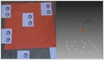
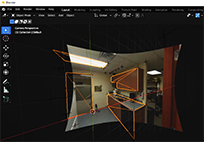
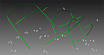
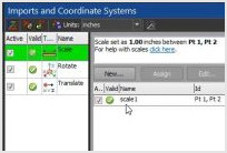
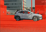
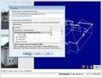
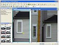
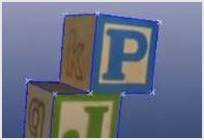
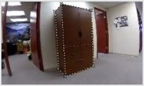
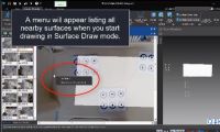
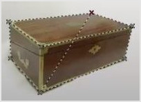
Surface Selection Menu

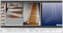
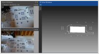
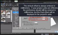
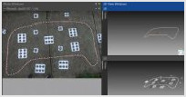
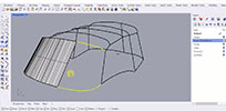
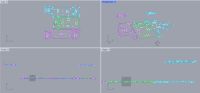
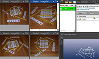
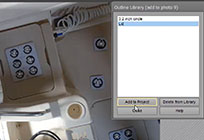
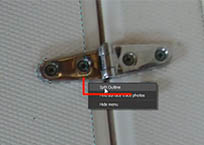
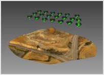
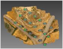
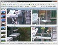
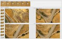
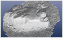
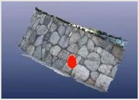
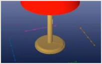
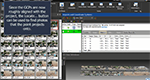
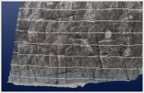
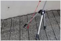
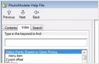
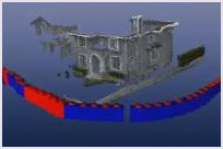
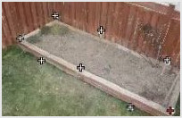
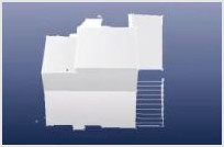
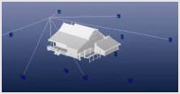
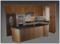
Starting in version 2021.1 there is a new method to help pick the surface you are doing surface draw on - using a pop up menu of close by surfaces.

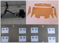
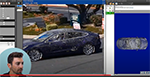
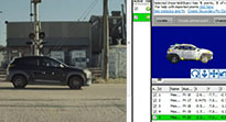
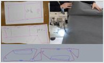
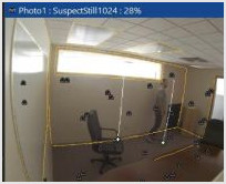
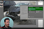
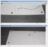
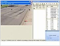
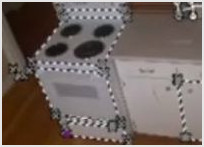
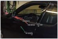
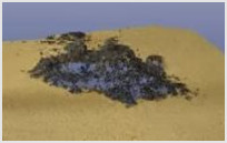
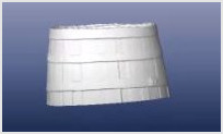
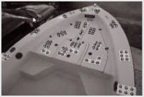
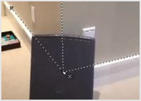
Surface Draw - fixing a wrong surface

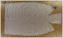
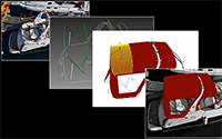
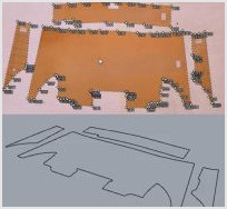
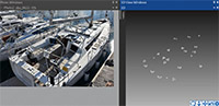
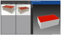
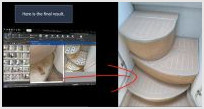
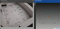
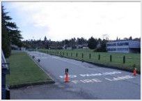
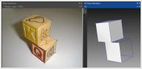
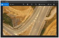
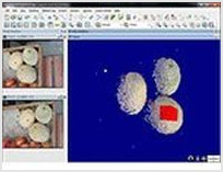
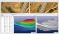
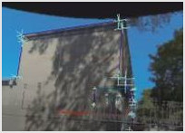
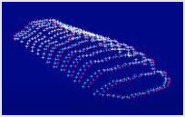
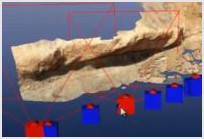
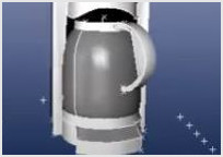
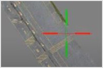
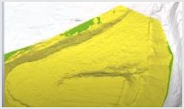
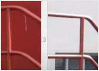
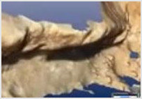
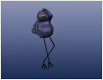
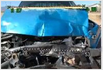
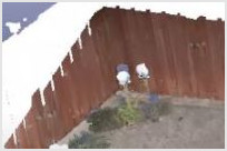
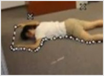
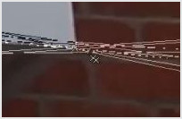
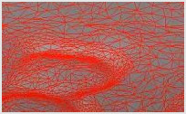
This video shows what happens when Surface Draw is place on the wrong surface (here outlining areas of boat decking), and how to fix it by assigning the correct surface. Surface Draw points, lines, or curves, assigned to a surface in PhotoModeler that does not match the true real-world surface will not calculate in the correct 3D position. This means, when they are viewed from on photos from other angles, their positions will not line-up and match. To fix this, the correct surface is assigned to the points and the correct 3D position are automatically calculated.

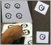
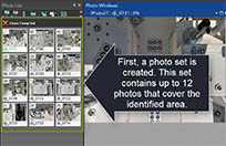
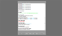
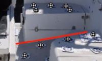
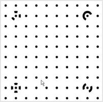
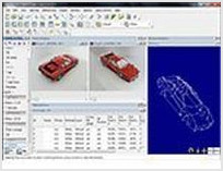
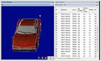
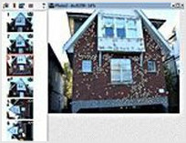
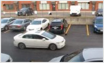
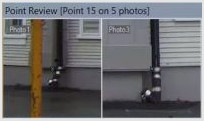
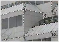
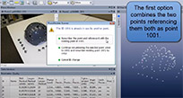
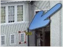
Troubleshooting high residuals

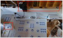
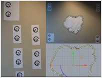
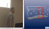
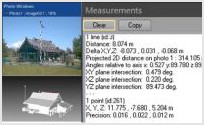
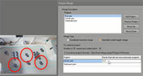
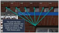
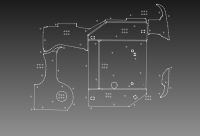
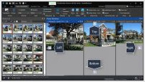
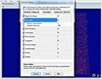
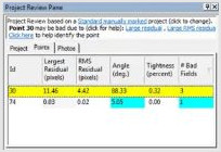
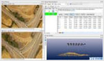
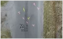
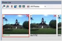
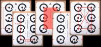
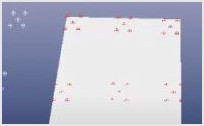
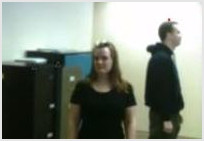
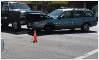
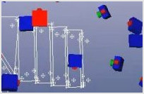
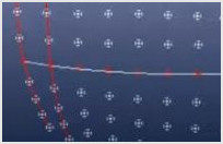
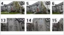
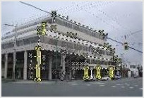
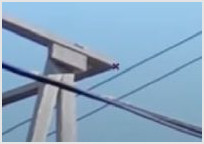
High mark residuals are often caused by incorrect references. This video describes a way to find incorrect references in a manually marked PhotoModeler project.

Back to top


Turning off auto-advance during referencing

During referencing mode the active reference point with-in the selected source points can automatically advance to the next point and will be reset to the start when you move to another destination photo. If you prefer to reference between several photos at once you can turn off auto-advance and manually control when the source point switches.

Use LIDAR to Help Solve a Single Photo Forensics Case

The video describes how PhotoModeler can use a 3D laser scan (LIDAR) of a crime scene to solve and extract information from a security / surveillance camera.

Use Photos to digitize clothing patterns for use with CLO

PhotoModeler's pattern capture add-on can be used to digitize pattern templates for use in the CLO (www.clo3d.com) fashion design software.

Back to top


Using a plane surface and a mesh to measure volume

Selecting a plane surface and a mesh returns the volume of the mesh above and below the plane.

Using Image Enhance

The Image Enhance pane can be used to bring out details that are hard to see. Adjust the image contrast, brightness or gamma to improve visibility of key details and help improve marking.

Using known XYZ data as multipoint transform or control

There are several ways to use known XYZ point data with in PhotoModeler. This video covers the two main uses, multipoint transforms and control points.

Back to top


Using lines to mark hidden corners

When a corner is hidden due to an occlusion you can use temporary lines to estimate where the corner lies.

Using multiple frames from a static camera position

If a camera(s) position remains fix and you would like to use multiple frames from this position you can replace the image data without needing to re-orient the photos. This can be useful when trying to obtain measurements from a security camera or when using a fixed camera set-up to measure a dynamic scene.

Using Photosets

Using photo sets to group images making work on large projects easier. A photo set is a grouping of photos that can be made visibile alone.

Back to top


Using Sphere targets to orient photos

Similar to dot targets, PhotoModeler can also detect the center of spheres located in the scene to accurately orient a set of photos.

Using Spheres to align laser scan data

When projects are solved using spherical targets and these sphere centers have been collected during a laser scan they can be used to align the scan data with the photos.

Using Surface Draw to Outline a Pool

PhotoModelers surface draw tools can be used to measure planar surfaces using a single photo. This video shows the steps to define the shape of a pool using a surface draw curve.

Back to top


Using Surface Draw to model a flat complex shape

Use PhotoModeler's Surface Draw tool to model and measure a complex shape that lies on a simple surface. The example uses a kitchen sink cutout but the technique can be applied to fields like boat decking, templating, forensics, building design, restoration, archaeology, etc.

Using tables

Using and configuring tables to display spreadsheet style project data.

Using tags to identify points

How to use tags to flag points of interest.

Back to top


Using the 3D Viewer view settings

This video highlights and shows the use of several view settings available with in PhotoModeler's 3D Viewer.

Using the curve through selected points tool

Instead of selecting individual points the curve through selected points tool will intelligently fit a curve through a group of points.

Using the name field

Use the name field to identify objects on photos, tables and in 3D.

Back to top


Using video input with SmartMatch projects

SmartMatch projects can automatically and intelligently extract frames from the video input, or you can manually extract key frames for use in any project type.

Using, showing and hiding Reference Helper Lines

Reference helper (epipolar) lines can be used to help establish a points location. The Show/Hide reference helper lines tool can be used to toggle their visibility.

View 3D wireframe overlayed on a shaded view

To view additional detail on a 3D surface you can overlay the shaded model with the triangled wireframe view.

Back to top


Viewing rays from points and cameras

The 3D viewers can be set to display the light rays used by a selected camera station or point. These rays give a visual indication of angles used to calculate the position of the selected objects.

Ways to arrange photos while referencing

Referencing mode has two ways to arrange the photos. This video shows both of them, highlighting the side-by-side option.

Ways to Open Photos Showing a point

PhotoModeler has several tools to identify photos related to a point. This video describes their use and different ways to help identify which photos are useful when creating 3D points.

Back to top


Zoom and center

PhotoModeler has several ways to adjust a photos zoom. The zoom and center command is a great one for reviewing point marks on several photos.


Back to top