
- /
- /
- /
Using Offset Points for Forensic Height Measurement
Introduction
This article describes a technique to estimate heights from a single photo of unknown source. It uses a new feature in version 6.1 called Offset Points. We simulate this situation using a photo taken from an uncalibrated 1.1 mega-pixel cell phone camera but the same steps apply to photos from other sources (e.g. security cameras, etc.).
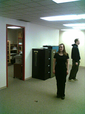
Using this photo we determine reasonably accurate height estimates for both people, and other potentially useful information such as their distance apart, distance to the doorway, and distance to some evidence lying on the floor.
As no information about the camera is known some information from the scene must be used to calculate the camera parameters using the Inverse Camera feature. Two techniques for inverse camera calculation are shown, one using shapes and another using control points. If the camera was available for calibration, inverse camera would not be needed but the shape and control points would still be needed to solve the single photo situation.
This article complements other information found in the PhotoModeler tutorial videos and Help File. A basic familiarity with PhotoModeler operation is assumed.
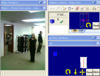
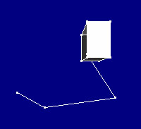
| Inverse camera using shapes: First we solve the project and camera parameters using a shape. Start a shapes-based project, import the image of the scene, and select an “unknown camera – solved by shapes”. As the camera was rotated when the image was taken, right click on the thumbnail and choose ‘properties of selected photo’. Change the photo’s rotation to ’-90 degrees’ so the image will be shown upright.To solve an inverse camera using shapes we need an object that takes up a reasonable amount of image space and matches one of the shape primitives. In this case we use a ‘box’ shape with the filing cabinet in the background. We add a box shape to the project and mark it on the photo. This gives us a solution for the camera’s position and focal length as shown on the right. |
 |
| The next step is to use surface draw to identify where the two people are standing. We start the surface draw on the bottom face of the file cabinet because it rests on the ground (the same plane the two people are standing on). To make the bottom face of the box visible we select the right face and set it’s hidden property. If the face was not hidden, the surface draw would be established on the surface closest to the camera, the right face. | 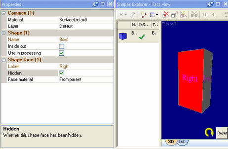 |
| Surface draw is marked on the photo starting in the area of the bottom of the cabinet. We use extended surface draw to identify where both people were standing on the floor.Using the Surface Draw Line tool we mark the points shown in red (starting with the one under the cabinet). | 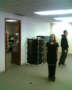 |
| This results in the 3d geometry as shown in the top down view (shown on the right):To perform proper measurements we need to add a scale. The filing cabinet height was measured as 52.25 inches, and we enter this as a scale in PhotoModeler. We can now determine the distance between any solved items in the model. Using the Measure tool we see that the man was standing 71.2 inches distant from the woman, and the woman was 34.5 inches from the evidence on the floor.
If no suitable shape primitive can be found in the photo you can also use a set of control points surveyed from the scene after the fact. The next section outlines the steps to do this. Following that, a technique to estimate the heights of both people is described (applicable to the shape or control points project). |
 |
| Inverse camera using control pointsStart a points-based project, import the image of the scene, and select an “unknown camera – solved by control points”.
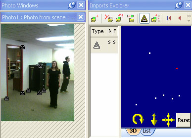
To solve an inverse camera or single photo using control points we import a survey of the scene. The control point information may be obtained through a survey of the scene, after the fact, as long as the items surveyed have not moved since the subject photo. This 3d survey can be done with PhotoModeler, multiple photos and a known camera or with a survey instrument like a total station. For this type of project one typically has five or more control points with a good spread over the photograph. We use the Imports Explorer to import the control data and mark it on the photo. This gives us a solution for the camera’s position and focal length. We check the residuals of the points to make sure they were marked correctly. |
 |
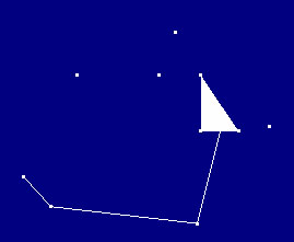
| Next we define the ground plane by creating a surface using the control points on the ground. Once the surface is created we can use surface draw to identify where on the ground each person is standing, just as we did when using the box shape.Using the Surface Draw Line tool, starting at the filing cabinet, we mark the points (shown in red) on the floor. |  |
| This gives us the following top-down view:Our scale and coordinate system is defined by the control points so we can perform measurements of the surface draw line segments without adding an additional scale. The measurements are similar to the shape solution.
The next step, of estimating the heights of the two people, is the same regardless of how the project has been solved (i.e. by shapes or by control points). |
 |
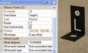
| Estimating heights using offsets:Offset points (a feature added in PhotoModeler version 6.1) are primarily used with targets that are placed near areas of interest but that can’t be directly marked.
For example, in the image on the right showing an Evidence Marker of known size, the red point is the offset point for the target. The offset point will be created 19 cm down the Z axis from the round marked target. This offset identifies the place on the ground directly below the target. The distance is entered in the project units, and is a negative value because the coordinate system has been defined so that the Z axis points up. Offsets can be assigned to regular points and surface draw points, as long as the points are 3D and a coordinate system has been defined (via scale/rotate or control points). In this case we will use offsets on the surface draw points to estimate the height of both people. |
 |
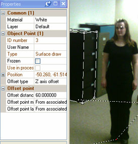
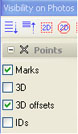 First turn on 3D offset point visibility.Then we select the point indicating where on the floor the female subject is standing and add a Z axis offset. We will start by guessing she is about 5 feet tall (60 inches). First turn on 3D offset point visibility.Then we select the point indicating where on the floor the female subject is standing and add a Z axis offset. We will start by guessing she is about 5 feet tall (60 inches).
This produces an offset point at around her eye level. So we know she is taller than 5 feet. |
 |
| Using trial and error we adjust the offset distance until the projected 3D offset point is at the top of her head.Our estimate puts her at about 63.5 inches (5’ 3.5”). Her actual height is 5’ 3”. | 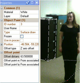 |
| Now we can do the same estimate for the male.His height in the image, where he is slightly slouched, is estimated at 71 inches (5’11”). His actual height is 6 foot. | 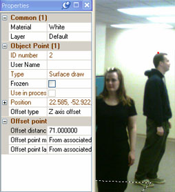 |
| The screen capture to the right shows the final result, showing the surface draw points of interest, as well as lines representing the height of the two people (lines connecting surface draw points with their offset points). | 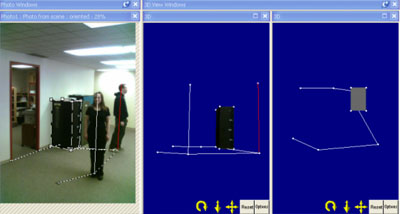 |
Summary
Using a low resolution image from a cell phone camera, that we knew nothing about, we were able to determine how tall and how far apart the two people were, as well as the distance to some evidence on the floor. We showed how to solve for the unknown camera parameters using shapes or control points, how to use surface draw to measure distances on a defined plane, and how to estimate heights using offset points.